Описание винтового компрессора Sabroe серии SAB 202
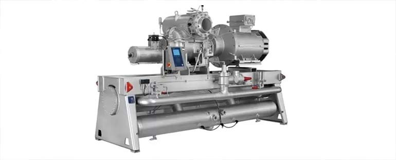
Компрессор SAB 202 представляет собой винтовой компрессор с регулируемой производительностью и системой впрыска масла.
Конструкция роторов компрессора Sabroe серии SAB 202
Два ротора (ведущий и ведомый) имеют асимметричный профиль зубьев в соответствии с лицензией SRM.
Особенности подшипников
Роторы оснащены подшипниками скольжения на стороне всасывания и комбинированным набором подшипников на стороне нагнетания.
Различные исполнения роторов
Роторы представлены в двух исполнениях для ведущего и ведомого приводов.
Система фильтрации и защиты
Компрессор оборудован встроенным всасывающим фильтром с защитным клапаном для предотвращения попадания загрязнений и непредвиденных давлений.
Система смазки и защиты масла
Для эффективной смазки подшипников в компрессоре используется фильтрующий патрон.
Предотвращение обратного вращения
Встроенный обратный клапан предотвращает обратное вращение компрессора при отключении питания.
Уплотнение вала
Ведущий вал имеет сальниковое уплотнение типа скользящего кольца для предотвращения утечек.
Регулирование производительности
Производительность компрессора регулируется бесступенчато с помощью золотникового регулятора.
Регулирование объемного отношения Vi
Система регулирования Vi позволяет оптимизировать работу компрессора при изменяющемся давлении. Регулировка Vi может производиться как вручную, так и автоматически в зависимости от типа компрессора.
Запасные части для компрессора SAB 202
| Pos | Designation | No | Part no |
| Complete compressor LF, aut. Vi | 4161-059 | ||
| Complete compressor LF, man. Vi | 4161-060 | ||
| Complete compressor LM, aut. VI | 4161-061 | ||
| Complete compressor LM, man, Vi | 4161-062 | ||
| Complete compressor SF, aut. VI | 4161-063 | ||
| Complete compressor S F, man. Vi | 4161-064 | ||
| Complete compressor SM, ant, Vi | 4161-065 | ||
| Complete compressor SM, man. Vi | 4161-066 | ||
| Compressor housing | |||
| 10-1 | Compressor housing (L) | 1 | 3011-009 |
| 10-2 | Compressor housing (S) | 1 | 3011-019 |
| Bearing cover at suction end | |||
| 20-1 | Bearing cover, female drive | 1 | 3013-089 |
| 20-2 | Bearing cover, male drive | 1 | 3013-110 |
| 21 | O-ring dia. 430,66×3,53, neoprene | 1 | 1331-117 |
| 22 | Innar sleeve, INA IR dia. 17/20×16 | 2 | 1514-018 |
| 23 | Washer dia. 25/16.5×4 | 4 | 2114-047 |
| 24 | mreaded plug with cottar 1/2 | 1 | 1343-027 |
| 25 | Dowty ring 025 | 1 | 1331-430 |
| 26 | Cylindrical screw M16×60 | 10 | 1413-436 |
| 27 | Cylindrical screw M 16×30 | 2 | 1413-429 |
| 28 | Cylindrical screw Ml 6×180 | 8 | 1413-428 |
| 30 | Hose connection | 1 | 1345-143 |
| Bearing cover at ditcharge end | |||
| 40 | Thrust cover/capacity regulating cylinder | 1 | 3013-150 |
| 41 | Cylinder screw M16×60 | 20 | 1413-436 |
| 42 | Washer dia. 35/16,5×4 | 4 | 2114-047 |
| 43 | O-ring dia. 151,93×3,53, neoprene | 1 | 1331-099 |
| 44 | Adjusting screw | a | 2111-128 |
| 45 | Locking screw M6×10 | 4 | 1413-231 |
| 46 | Cross bar for bearing adjustment | 1 | 3083-137 |
| 47 | Cylinder screw M12×30 | 6 | 1413-366 |
| 48 | Inner sleeve, INA IR dia 17/20×16 | 2 | 1514-018 |
| 49 | O-ring dia. 13,94×2,62 | 1 | 1331-014 |
| Cover for capacity regulating cylinder | |||
| 60 | Cover for capacity cylinder | 1 | 3013-197 |
| 61 | O-ring dia. 142,47×3,53 — neoprene | 1 | 1331-096 |
| 62 | Cylinder screw M12×35 | 4 | 1413-387 |
| Housing for capacity indicator | |||
| 70 | Housing for capacity indicator | 1 | 3045-002 |
| 71 | Cylinder screw M6×30 | 4 | 1413-343 |
| 72 | Cover for capacity indicator | 1 | 3045-003 |
| 73 | Cylinder screw M6×50 | 4 | 1413-347 |
| 74 | O-ring dia. 98.02×3,53, neoprene | 1 | 1331-081 |
| 75-1 | Glass for indicator (L) | t | 3045-050 |
| 75-8 | Glass for indicator (S) | 1 | 3045-049 |
| Rotors | |||
| 110-1 | Set of rotors tor SM | 1 | 3024-102 |
| 110-2 | Set of rotors tor SF | 1 | 3024-097 |
| 110-3 | Set of rotors for LM | 1 | 3024-103 |
| 110-4 | Set of rotors for LF | 1 | 3024-095 |
| 111 | Journal bearing | 4 | 1515-031 |
| 112 | Retaining pin for journal bearing dia, 5×45 | 4 | 1446-033 |
| 113 | Cylinder screw M6×45 | 8 | 1413-340 |
| 114 | Thrust washes | 2 | 3021-029 |
| 115 | Cylinder screw M16×45 | 2 | 1413-433 |
| 132 | Four point ball bearing dia. 70/150×35 | 2 | 1513-040 |
| 133 |
Set of shims dia. 128/150 for adjusting the clearance between the rotor and outlet port. Comprising:1 offthickness 5,60 mm |
2 | 3021-043 |
| 1-5,65 mrr | |||
| 1-5,70 mm | |||
| 1-5,75 mm | |||
| 1-5,80 mrn | |||
| 1-5,85 mm | |||
| 1-5,90 mm | |||
| 134 | Balance piston. drive rotor | 1 | 3025-052 |
| 135 | Spacer ring, drive rotor | 1 | 3025-035 |
| 136 | Retaining ring 4×10 | 1 | 1446-012 |
| 137 | Balance piston, driven rotor | 1 | 3025-034 |
| 138 | Spacer ring, driven rotor | 1 | 3025-036 |
| 139 | Retaining pin 5×16 | 1 | 1446-021 |
| DIscharga ports | |||
| 140-1 | Discharge port for male rotor . | 1 | 3031-031 |
| 141-1 | Discharge port for female rotor | 1 | 3031P032 |
| 142 | Cylinder scraw M8×190 | 6 | 1413-309 |
| 143 | Washer for discharge port dia. 16,5 /8,2×10 | 6 | 2114-045 |
| 144 | Cylinder screw M6×30 | 2 | 1413-343 |
| 145 | Pointed screw M10×35 — inside adjustment | 2 | 1413-255 |
| 146 | Locking screw M10×10 — inside adjustment | 2 | 1413-253 |
| 147 | Locking screw M10×10 — outside adjustment | 2 | 1413-253 |
| 148 | Pointed screw M10×20 — outside adjustment | 2 | 1413-032 |
| 149A | Blank of screw 3/8″ — outside adjustment | 2 | 1343-026 |
| 149B | Gasket — outside adjustment | 2 | 1331-427 |
| Parts for adjusting rotors | |||
| 153 | Inner cover | 2 | 3021-030 |
| 154 | O-ring dia. 142,47×3,53 | 2 | 1331-096 |
| 155 | Cylindrical steel roll 8H 11×8 | S | 1514-019 |
| Shaft seal | |||
| 160A | Shaft seal collar 1 | ||
| 160B | Shaft saal seat 1 | ||
| 160C | O-ring for shaft seat collar1 | 1 | 3084-557 |
| 160D | O-rlng for shaft saal seat1 | ||
| 160E | Pointed screw 3 | ||
| 161 | Retaining pin for shaft seal seat dia. 3×5 | 1 | 1446-005 |
| 162 | Spirolox ring (oil thrower) | 1 | 1437-294 |
| 163-1 | Cover, F | 1 | 3013-100 |
| 163-2 | Cover, M | 1 | 3013-102 |
| 164 | O-ring dia, 132,94×3,53, neoprene | 1 | 1331-093 |
| 165-1 | Cover for shaft seal, F | 1 | 3013-099 |
| 165-2 | Cover for shaft seal, M | 1 | 3013-101 |
| 166 | O-ring dia, 158,34×3,53 | 1 | 1331-100 |
| 167 | Cylinder screw M12×35 | 8 | 1413-387 |
| 168 | Hose connection branch 1 /4° | 1 | 1345-143 |
| 169 | Clear plastic hose | 1 | 1241-190 |
| Suction filter | |||
| 170 | Suction filter | 1 | 3042-075 |
| Adjusting system for Vi-slide, AUT | |||
| 352 | Screw for transmitter M3×8 (included in pos. 410) | (4) | 1412-012 |
| 371 | Sealing ring OD 70 | 1 | 1332-126 |
| 372 | Attachment for pin | 1 | 3044-035 |
| 380 | Cover tor aut. Vi | 1 | 3013-196 |
| 381 | O-ring dia. 101,19×3,53, neoprene | 1 | 1331-083 |
| 382 | Cylinder screw M12×35 | 4 | 1413-387 |
| 384 | Attachment for sealing ring | 1 | 3044-034 |
| 385 | Cylinder screw M4×16 | 2 | 1413-320 |
| 386 | Cylindrical pin dia. 6×16 | 2 | 1445-076 |
| 387 | Cylinder screw M6×12 | 1 | 1413-339 |
| 390 | Spindle aut. Vi | 1 | 3044-063 |
| 393 | Ball baaring 6202 | 1 | 1511-012 |
| 395 | Driving disk | 1 | 3044-021 |
| 396 | Cylinder screw M4×12 | 1 | 1413-318 |
| 400 | Attachment tor transmitter | 1 | 3044-064 |
| 401 | Cylinder screw M6×80 | 4 | 1413-307 |
| 402 | Cover ring for transmitter | 1 | 3045-009 |
| 403 | Cylinder screw M4×10 | 4 | 1413-319 |
| 405 | Magnetic coupling | 1 | 3045-062 |
| 406 | O-ring dia. 32,99×2,62 (incl in pos. 405) | (1) | 1331-133 |
| 407 | Hexagon head screw M4×16 (inc. in pos. 405) | (1) | 1413-320 |
| 410 | Turning transmitter | 1 | 3448-004 |
| 411 | Driving lug | 1 | 3044-020 |
| 412 | Pointed screw M4×5 | 1 | 1413-211 |
| 413 | Clamping pin dia. 1,5×12 | 1 | 1446-010 |
| Adjusting system for Vi-slide, MAN | |||
| 180 | Spindle man. Vi | 1 | 3044-052 |
| 181 | Cover for man. Vi | 1 | 3013-093 |
| 182 | Sealing washer for slide stop | 1 | 3044-014 |
| 183 | Sealing ring | 1 | 1331-503 |
| 184 | O-ring dia. 44,04×3,53, neoprene | 1 | 1331-065 |
| 185 | Retainer for bearings | 1 | 3044-033 |
| 186 | Axial ball bearing dia. 42/25×11 | 2 | 1512-015 |
| 187 | Locking plate | 1 | 2114-043 |
| 188 | Cylinder screw M6×12 | 1 | 1413-339 |
| 189 | Thread washer | 1 | 3044-073 |
| 195 | Cylinder screw M4×30 | 2 | 1413-325 |
| 196 | Cylinder screw M6×35 | 3 | 1413-344 |
| 197 | O-ring dia. 101,19×3,53 | 1 | 1331-083 |
| 198 | Cylinder screw M12×35 | 4 | 1413-387 |
| Vi-slide | |||
| 190-1 | Slide stop, S | 1 | 3043-131 |
| 190-2 | Slide stop, L | 1 | 3043-130 |
| 191-1 | Spring for Vi-slide,L | 1 | 2144-042 |
| 191-2 | Spring for Vi-slide,S | 1 | 2144-043 |
| 192 | Cylinder screw M 10×25 | 1 | 1413-371 |
| Capacity regulating slide | |||
| 200-1 | Slide for L | 1 | 3043-113 |
| 200-2 | Slide for S | 1 | 3043-125 |
| 201 | Piston part inner | 1 | 3043-138 |
| 202 | Piston part outer | 1 | 3043-139 |
| 203 | O-ring dia. 40,87×3,53, neoprene | 1 | 1331-064 |
| 204 | Sealing ring dia. 150 | 1 | 1332-133 |
| 206 | Slotted nut KM8 | 1 | 1514-200 |
| 207A-1 | Piston rod for L | 1 | 3043-140 |
| 207A-2 | Piston rod for S | 1 | 3043-141 |
| 207B | Bushing tor indicator spindleIncluded in pos. 207A | 1 | 3045-046 |
| 207C | Cylindrical pin dia. 6×16 Included in pos. 207A | 1 | 1445-076 |
| 207D | Spirolox-ring Inducted in pos. 207A | 1 | 1437-291 |
| 207E | Steel ball 3/8″ Included in pos. 207A | 1 | 1514-158 |
| 208 | Locking plate for slotted nut | 1 | 1514-070 |
| 209 | Tape bearing | 2 | 2132-100 |
| 311 | Cap torew M20×60 | 1 | 1424-289 |
| 313 | Clamp | 1 | 3042-054 |
| Spindle for copacity indication | |||
| 210 | Spindle for copacity indication | 1 | 3045-059 |
| 216 | Magnetic coupling | 1 | 3045-061 |
| 217 | O-ring dia. 44,12×2,62 (incl. in pos. 216) | (1) | 1331-146 |
| 218 | Hexagon head screw M4×16 (Incl. in pos. 216) | (1) | 1413-320 |
| 219 | Hexagon head screw M4×20 (ind. in pos. 216) | (2) | 1413-322 |
| Capacity indication | |||
| 221 | Indication disk | 1 | 3045-001 |
| 223 | Socket cap screw M4×10 | 1 | 1413-319 |
| 224 | Backing ring 105/90×1,6 | 1 | 2356-155 |
| 226 | Locking washer DC 15/8,4 | 1 | 1437-054 |
| 227 | Locking washar DC 8/4,3 | 1 | 1437-060 |
| 350 | Position transmitter | 1 | 3448-004 |
| 351-1 | Indicator glass, L (replacing pos. 75-1 when transmitter) | 1 | 3045-048 |
| 351-2 | Indicator glass, S (replacing pos. 75-2 whentransmitter) | 1 | 3045-047 |
| 352 | Screw for transmitter M3×8 (incl. in pos. 350) | (4) | 1412-012 |
| Non return valve | |||
| Non return valve complet | 3042-172 | ||
| 252 | O-ring dia. 253,37×5,33, neoprene | 1 | 1331-181 |
| 253 | Intermediate flange | 1 | 3013-288 |
| 255 | Valve housing | 1 | 3042-127 |
| 256 | Spindle guide | 1 | 3042-125 |
| 257 | Retainer | 1 | 3042-126 |
| 258 | Hexagon head screw M8×120 | 3 | 1413-314 |
| 259 | Valve cone | 1 | 3042-123 |
| 260 | Spindle | 1 | 3042-124 |
| 261 | Spring | 1 | 1523-033 |
| 262 | Tape bearing dim 10×1 x 46 | 1 | 2132-114 |
| 263 | Tape bearing dim 10×1 x 105 | t | 2132-096 |
| 264 | Hexagon head screw M16×75 | 8 | 1424-108 |
| 265 | Countersunk socket cop. screw M12×25 | 1 | 1413-115 |
| 266 | Hexagon bead scraw M12×30 | 2 | 1413-386 |
| 267 | Shaft nut KM9 — M45 | 1 | 1514-201 |
| 268 | Seeger ring dia. 14×1,0, DIN 471 | 1 | 1437-207 |
| Oil injection | |||
| 316 | V-joint 22-RL | 1 | 1349-153 |
| 317 | Check valve RVS | 1 | 1364-163 |
| 318 | O-ring dia. 33,05×1,78 | 1 | 1331-123 |
| 319 | Valve seat | 1 | 3042-077 |
| External oil piping | |||
| 320-1 | Pipe sat (L) | 1 | 3049-026 |
| 320-2 | Pipe sat (S) | 1 | 3049-029 |
| 321 | Pipe clamp dia. 3×12 | 1 | 2532-012 |
| Oil filter | |||
| 450 | Oil filter cover | i | 3041-008 |
| 452 | O-ring dia. 132,94×3,53, neoprene | 1 | 1331-093 |
| 453 | O-ring dia. 101,19×3,53, neoprene | 1 | 1331-083 |
| 455 | Lock nut M10 | 1 | 1433-030 |
| 456 | Cylinder screw M12×35 | 4 | 1413-387 |
| 458 | Stay bolt for magnet | 1 | 2111-127 |
| 459 | Magnets for oil filter | 4 | 1517-022 |
| 460 | Intermediate ring | 4 | 3424-039 |
| 461 | Rubber ring | 2 | 1334-012 |
| 462 | Plug 1/4″ | 2 | 1343-025 |
| 463 | Dowty ring dia. 20,57×13,74 | 2 | 1331-428 |
| 470 | Oil filter cartridge | 1 | 1517-015 |
| 475 | O-ring dia. 63,9×3,53 | 1 | 1331-071 |
| 476 | Cylinder screw M 12×30 | 4 | 1413-386 |
| Oil flow swich | |||
| 500 | Terminal box | 1 | 1554-001 |
| 501 | Cover for flow switch | 1 | 3041-004 |
| 502 | O-ring dia. 132,94×3,53, nroprere | 1 | 1331-093 |
| 505 | Nipple tor ftow switch o | 1 | 2314-106 |
| 506 | Dowty ring | 1 | 1331-433 |
| 507 | Flow switch with ball | 1 | 1553-024 |
| 508 | Washer | 1 | 2114-046 |
| 509 | Gasket dia. 19/14×1,5 | 1 | 2356-124 |
| 510 | Spring | 1 | 2144-041 |
| 511 | Circlip (included in pos. 507) | 1 | |
| 512 | Cylinder screw M12×35 | 4 | 1413-387 |
| Plugging | |||
| 520 | Plug 1/2″ | 1 | 1343-027 |
| 521 | Dowty ring 025 | 1 | 1331-430 |
| 525 | Plug 3/4″ | 1 | 1343-028 |
| 526 | Dowty ring 027 | 1 | 1331-433 |
| 530 | Plug 1/4″ | 1 | 1343-025 |
| 531 | Gasket ring 19/14×1,5 | 1 | 2356-124 |
| Economizer inlet | |||
| 600 | Eco-plug | 1 | 3013-111 |
| 601 | Cylinder screw M12×30 | 4 | 1413-386 |
| 602 | Cylinder screw M8×30 | 2 | 1413-358 |
| 603 | O-ring dia. 53,57×3,53, neoprene | 1 | 1331-058 |
| Relief valve | |||
| 700-1 | Back pressure independent valve. BSV 8-18 bar | 1 | 2416-202 |
| 700-2 | Back pressure independent valve. BSV 8-22 bar | 1 | 2416-224 |
| Pilot operated valve | |||
| 701-A | Connection line for POV 50 | 1 | 3049-032 |
| 701-B | Connection line for POV 60 | 1 | 3049-033 |
| 702-A | Cylinder screw M12×25 | 4 | 1413-385 |
| 702-B | Cylinder screw M 12×30 | 4 | 1413-388 |
| 703-A | O-ring dia. 63,09×3,53 | 1 | 1331-071 |
| 703-B | O-ring dia. 88,49×3,53 | 1 | 1331-079 |
| 704-A | Pilot operated valve, POV 50 (for R717) | 1 | 2417-046 |
| 704-B | Pilot operated valve, POV 80 (for R22 and HCF,s) | 1 | 2417-058 |
| Cover for main valve | |||
| 705-A | Cover for POV 50 | 1 | 3013-125 |
| 705-B | Cover for POV 80 | 1 | 3013-163 |
| 706 | Cylinder screw M16×40 | 8 | 1413-432 |
| 707 | O-rlng dia. 253.37×5,33 | 1 | 1331-181 |
| Connection between compr. discharge side and suction side | |||
| 710-A | Manifold for POV 50 | 1 | 3013-124 |
| 710-B | Man (fold tor POV 80 | 1 | 3013-157 |
| 711-A | O-ring dia. 85,32×3,53 | 1 | 1331-078 |
| 711-B | O-ring dia. 86,49×3,53 | 1 | 1331-079 |
| 712-A | Cylinder screw M12×110 | 3 | 1413-406 |
| 712-B | Cylinder screw M12×30 | 4 | 1413-386 |
| 715-A | Cover (for POV 50 only) | 1 | 3013-125 |
| 716 | Cylinder screw M16×40 | 4 | 1413-432 |
| 717 | O-ring dia. 164,69×3,53 | 1 | 1331-101 |
| 720-A | Pipe conneclion for POV 50 | 1 | 3014-002 |
| 720-B | Pipe connection for POV 80 | 1 | 3013-166 |
| 721-A | Cylindar screw M12×30 | 8 | 1413-386 |
| 721-B | Cylinder screw M12×40 | 4 | 1413-388 |
| 722-A | O-ring dia. 75,79×3,53 | 2 | 1331-075 |
| 722-B | O-ring dia. 88.49×3,53 | 1 | 1331-079 |
| Releif valve connections | |||
| 725 | Stud coupling A-12 RL | 1 | 1349-053 |
| 726 | Al-gasket dia.24/13×1,5 | 1 | 2356-127 |
| 727 | Reducer G3/4 — G3/8 | 1 | 2312-038 |
| 729 | Elbow coupling VB 12-RL | 1 | 1349-210 |
| 730 | Union nut G1 | 1 | 2313-017 |
| 731 | Threaded nipple G3/8 | 1 | 2311-065 |
| 732 | Al-gastet dia.30/16×1,5 | 1 | 2356-137 |
| 733 | Dowty ring 023 | 1 | 1331-427 |
| Signal trantducers | |||
| 751 | Pressure transducer, PT1 | 1 | 1373-249 |
| 752 | Pressure transducer, PT3 | 1 | 1373-271 |
| 753 | Pressure transducer, PT4 | 1 | 1373-271 |
| 755 | Stud coupling | 2 | 1349-137 |
| 756 | Stud elbow | 1 | 1349-233 |
| 761 | Temperature transmitter, TT6 | 1 | 1373-264 |
| 762 | Temperature transmitter, TT7 | 1 | 1373-264 |
| 765 | Gasket ring | 2 | 1349-135 |
| 766 | Reducer G1/2-G1/4 | 1 | 1349-077 |
Получить более подробную информацию Вы можете обратившись к нашим специалистам по e-mail: Адрес электронной почты защищен от спам-ботов. Для просмотра адреса в вашем браузере должен быть включен Javascript. или заполнив форму на странице «обратная связь».